Pulse Output Device (POD) Installation
When ordered as part of a meter system with a Register, the Liquid Controls Pulse Output Device (POD) is typically installed onto the meter and wired to the Register at the factory. The POD can also be ordered separately and installed onto meter systems already in service. For mechanical installation instructions, refer to the POD manual. Instructions for wiring the POD to the Register are given below.
Disconnect Power |
Disconnect the power before working on the CPU board. |
These materials are necessary, but are not supplied with the POD:
•16-22 AWG 4 conductor Shielded Cable (Consult the POD manual for complete specifications)
•Weather Proof flexible conduit or loom
•½” Conduit connectors or cable glands
•PTFE tape or thread sealant
Single Channel Pulse Inputs
The Register is compatible with the many single channel pulse output devices.
To wire a single channel pulse output to the Register:
1.Go to Main Menu / Setup Menu / Meter Settings. Select Pulse Input Type, Single Channel.
2.Connect the three pulser terminals (V out, Channel A, and ground) as follows:
•Pulser channel A to Register terminal 69
•Pulser voltage out to Register terminal 70
•Pulser ground to Register terminal 63
New Installations
 |
When ordered with the flowmeter, the POD comes factory installed on the meter and ready for wiring. Wiring instructions begins on page 10. |
 |
RELIEVING INTERNAL PRESSUREAll internal pressure must be relieved to zero pressure before disassembly or inspection of the strainer, vapor eliminator, any valves in the system, the packing gland, and the front or rear covers. Serious injury or death from fire or explosion could result in performing maintenance on an improperly depressurized and evacuated system. Strictly follow this procedure Relieving Internal Pressure Procedure for LPG and NH3 Meters: 1.Close the belly valve of the supply tank. 2.Close the valve on the vapor return line. 3.Close the manual valve in the supply line on the inlet side of the meter. If no manual valve exists on the inlet side, consult the truck manufacturer for procedures to depressurize the system. 4.Slowly open the valve/nozzle at the end of the supply line. 5.After product has bled off, close the valve/nozzle at the end of the supply line. 6.Slowly crack the fitting on top of the differential valve to relieve product pressure in the system. Product will drain from the meter system. 7.As product is bleeding from the differential valve, slowly reopen and close the valve/nozzle on the discharge line. Repeat this step until the product stops draining from the differential valve and discharge line valve/nozzle. 8.Leave the discharge line valve/nozzle open while working on the system. |
Retrofit Installations
Follow these procedures to remove the existing hardware:
1.Relieve the pressure from the process piping to the meter. 2.Drain the meter by opening the meter’s drain plugs. 3.Remove the mechanical counter, adjuster, and adjuster drive shaft from the front of the meter. 4.Some meters have a counter adapter bracket which is bolted on. If this is the case, remove the counter bracket by removing the bolts that hold it in place. If the counter adapter bracket is integral to the meter, it cannot be removed. In this case, one of four POD Pulser Extensions will be required. |

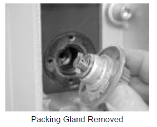 |
1.Remove the packing gland mounting screws. Pull the packing gland out of the meter. If the O-Ring does not come out with the packing gland, be sure to remove it from the packing gland well before installing the POD.
Installing the POD
POD Extension Kits |
If a POD Extension Kit is necessary, it must be installed prior to installation of the POD. See POD Extension Kit Installation. |
Follow these steps to install the POD onto a flowmeter:
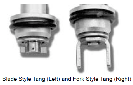
1.Verify that the proper POD Model was obtained by comparing the driver tang on the POD to the driver tang on the packing gland that was removed in Step 5 of the Retrofit Installations section above. There are two types of packing gland/POD driver tangs: blade type and fork type. Blade type packing glands must be replaced with blade type PODs. Fork type packing glands must be replaced with fork type PODs. 2.Determine the desired orientation of the conduit hub. The hub can be positioned in one of eight possible orientations as shown in the figure to the right. 3.Position the O-Ring over the bottom of the POD as shown to the right. 4.Align the fork style or blade style driver with the drive mechanism in the meter and guide the POD into the opening in the meter cover. When properly aligned, the POD will go in until its mounting flange abuts the meter cover. 5.Rotate the POD to the desired orientation and thread in the mounting screws until they are snug. Using a ⁷⁄₃₂" box end wrench, tighten the screws and torque them to 21-25 inch-pounds. |
 |

Wiring the Pulse Output Device to a register
Follow these steps:
1.Go to to Main Menu / Setup Menu / Meter Settings. Make sure Pulser Input Type is set to Dual Channel.
2.Attach cable glands and/or conduit connectors to the POD and the Register port(s). Make sure to use thread sealant on NPT threads.
3.Thread the wires through a piece of weatherproof conduit cut-to-length from the POD port to a Register port.
4.Run the weatherproof conduit between the POD and the Register housing, pull the wires through the ports, and tighten the connectors.
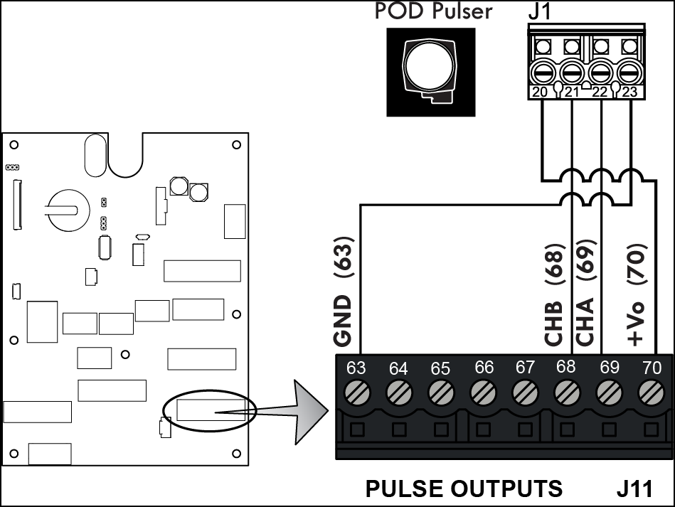
5.Connect the four POD terminals to four terminals on the J11 terminal block of the Register CPU board.
•POD terminal 20 to Register terminal 70
•POD terminal 21 to Register terminal 68
•POD terminal 22 to Register terminal 69
•POD terminal 23 to Register terminal 63